Control PCB, RF sensing integration, embedded interface, firmware, and matching control
In this build
Overview
The CMU Hacker Fab develops low-cost, open-source alternatives to democratize nanofabrication and replace expensive semiconductor manufacturing equipment. One of its core tools is a DIY RF sputtering chamber, where plasma conditions make the chamber impedance shift throughout a deposition run.
Traditionally, an operator keeps tuning variable capacitors by hand to reduce reflected power, measured as VSWR (Voltage Standing Wave Ratio). Commercial automated matching networks typically cost $3,000–$8,000+, making them a poor fit for a student-run fab. This project built a custom automated RF matching network to remove that manual tuning step at a much lower cost.
System Overview
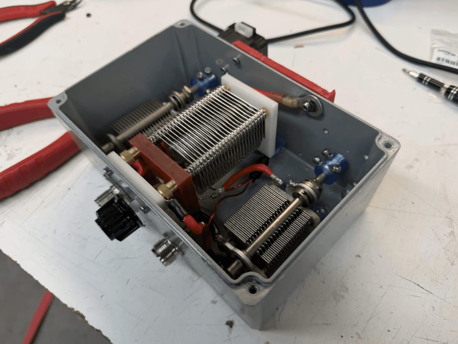
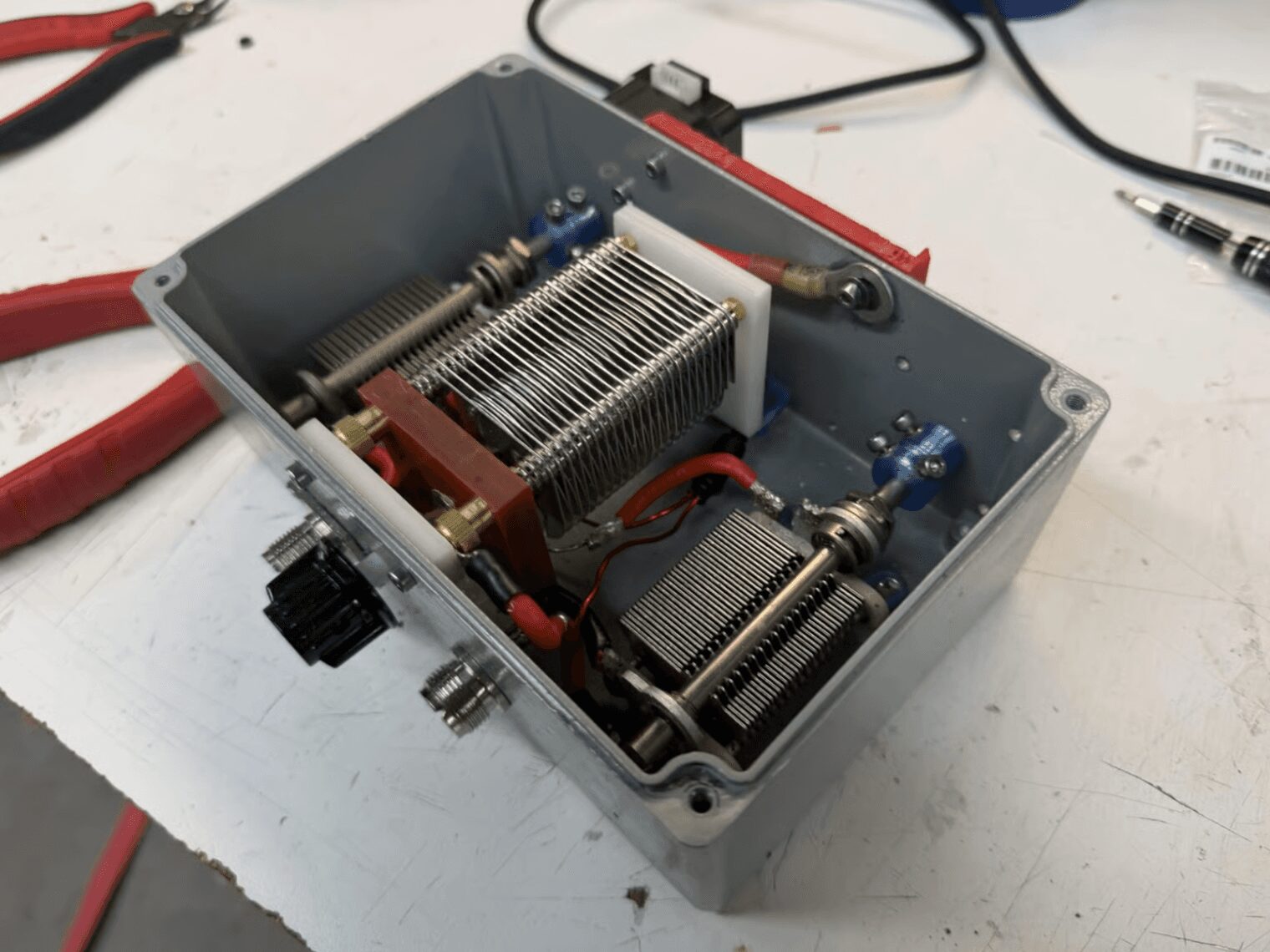
The matcher replaces manual knob-turning with high-precision digital control. A Teensy 4.1 and custom T-network read forward and reverse power signals from the RF line, then drive 0.9° stepper motors at 1/64 microstepping connected to air-variable capacitors.
A closed-loop controller searches capacitor positions in real time so the chamber stays matched as plasma conditions drift, without an operator on the knobs.
Actuation
0.9° NEMA 17 steppers at 1/64 microstepping
Network
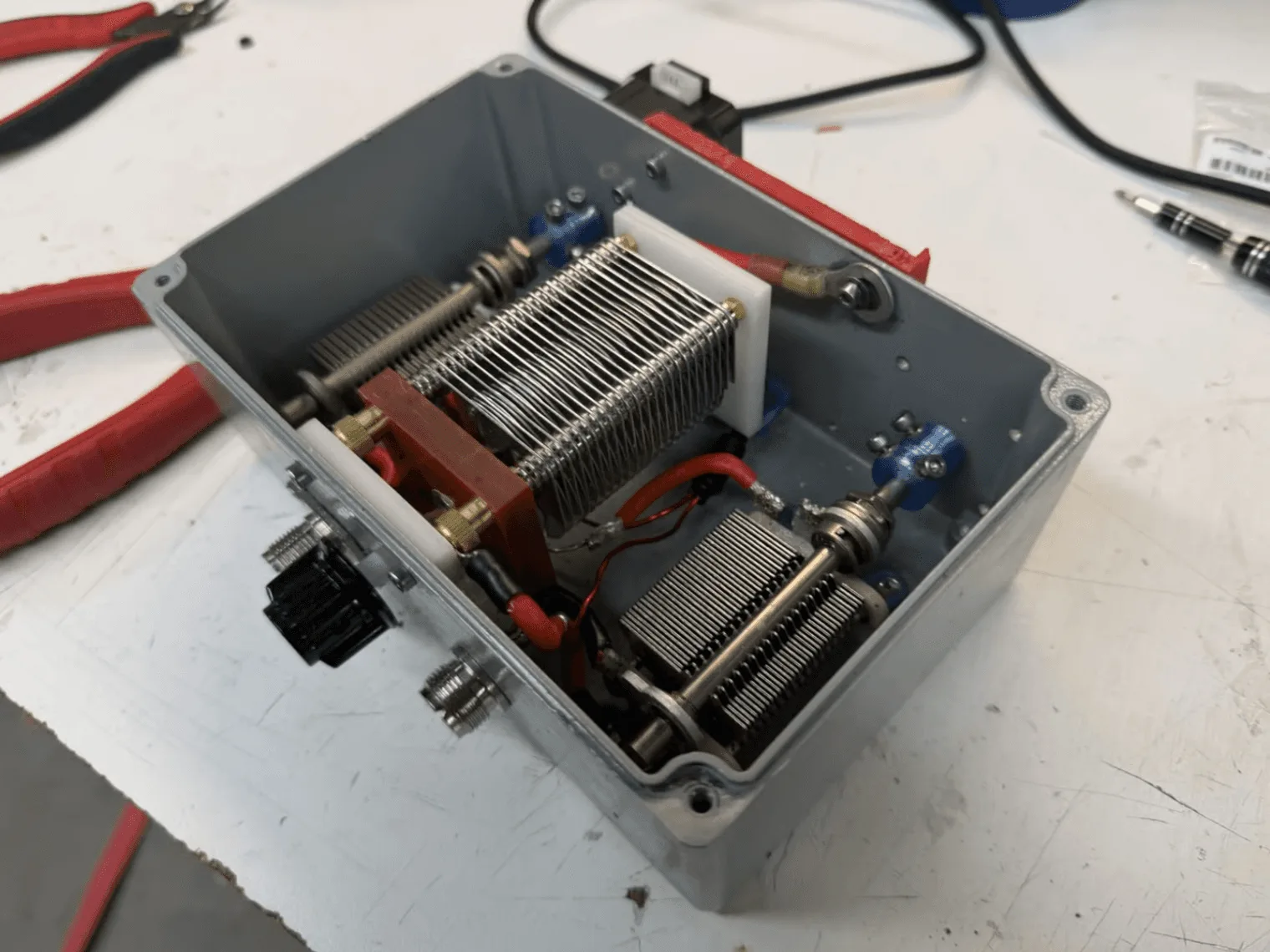
T-network with 500 V air-variable caps and a custom ~2 µH coil (6 turns, 16 AWG)
Match speed
~5 s from cold startup to lock
Sensing noise
±0.001 VSWR after buffering and supersampling
Watch video on YouTubeClosed-loop tuningVideo: automated matching converges toward the target VSWR.
PCB Design
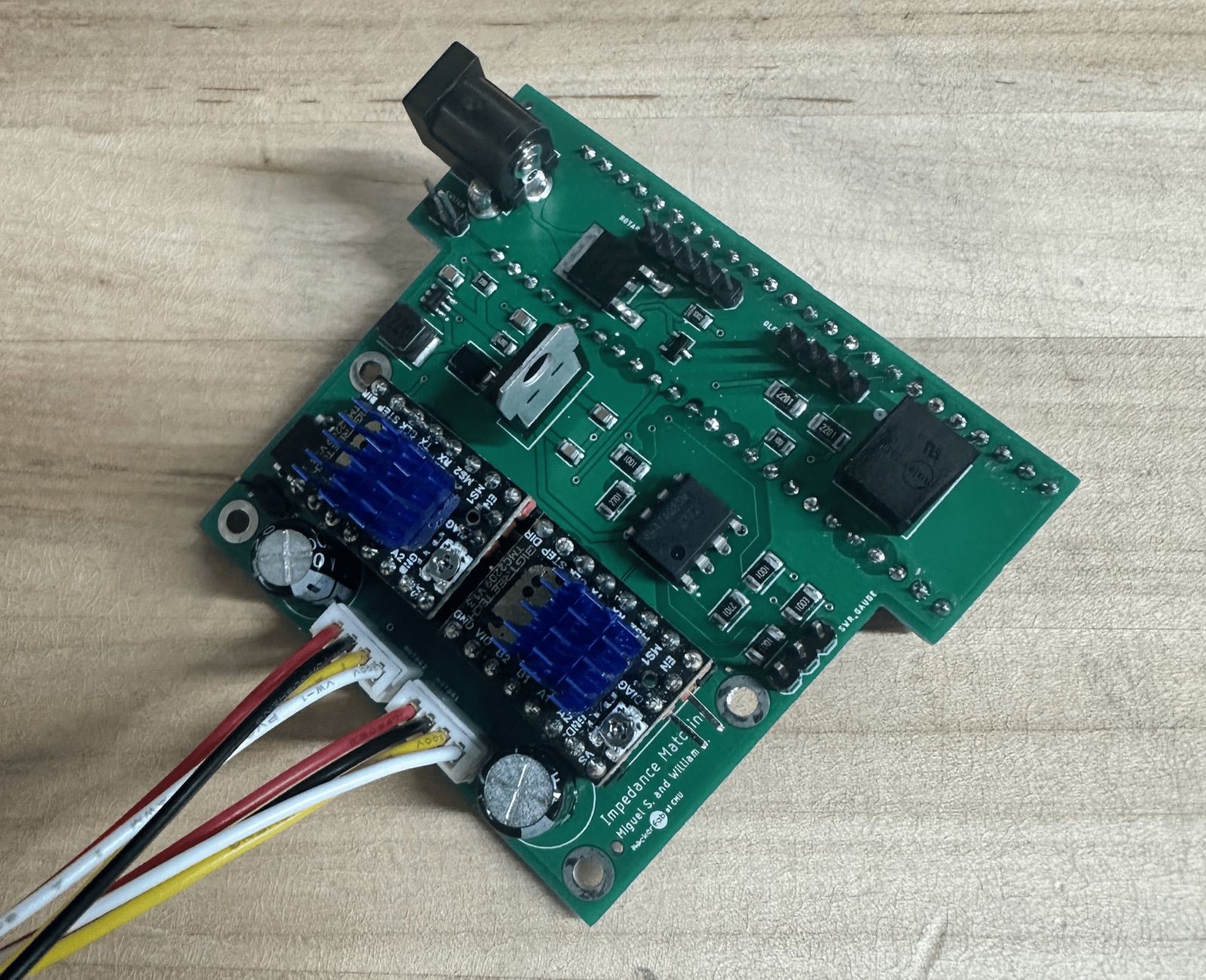
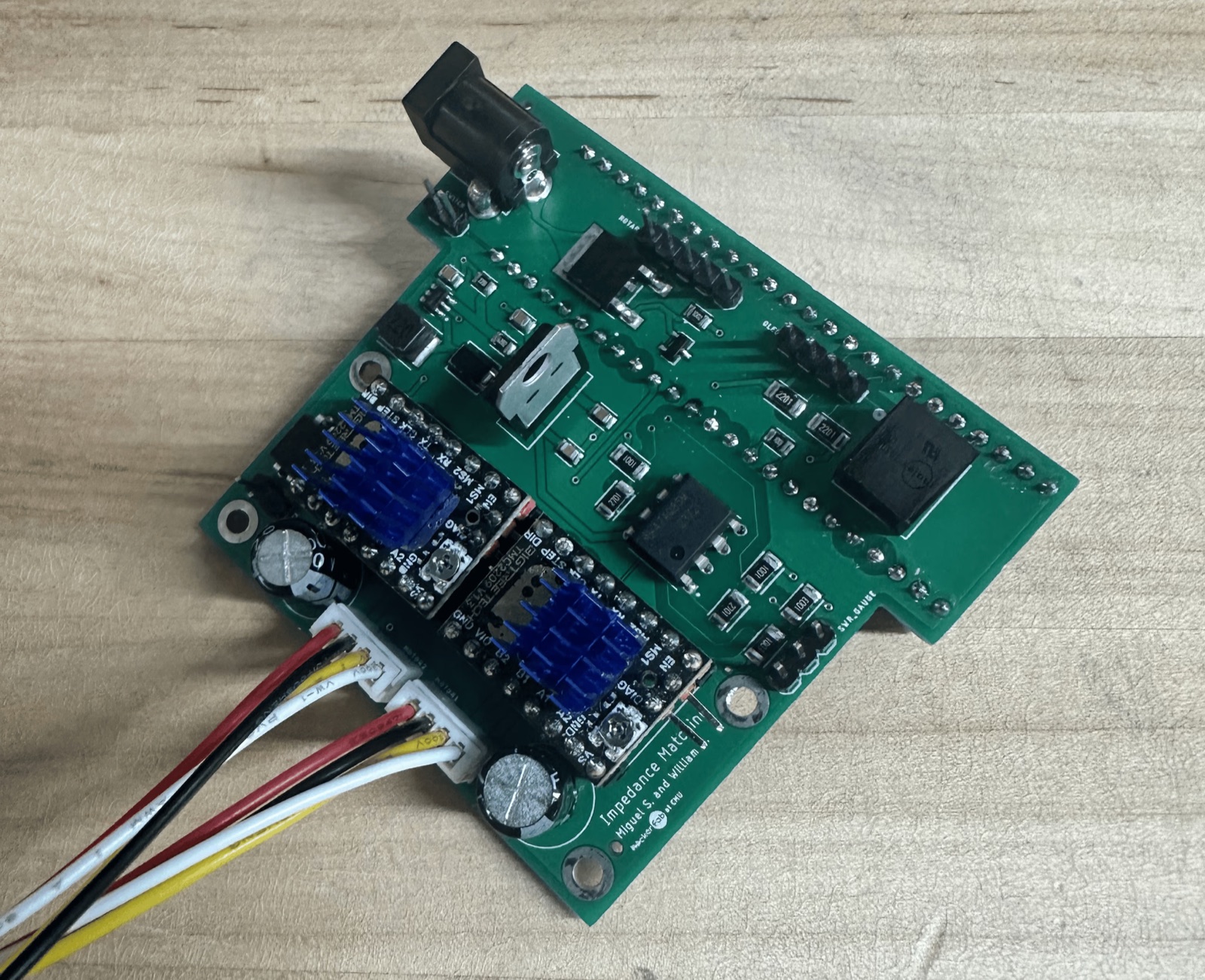
I designed a custom two-layer PCB around the Teensy 4.1, motor drivers, and active cooling. The board needed careful shielding and grounding to suppress RF interference in the feedback loop, keeping the microcontroller and drivers reliable in a high-noise environment.
Pointer: drag to pan and wheel to zoom. Touch: drag and pinch. Keyboard: Tab to the labeled viewer controls or switch views below.Source on GitHub
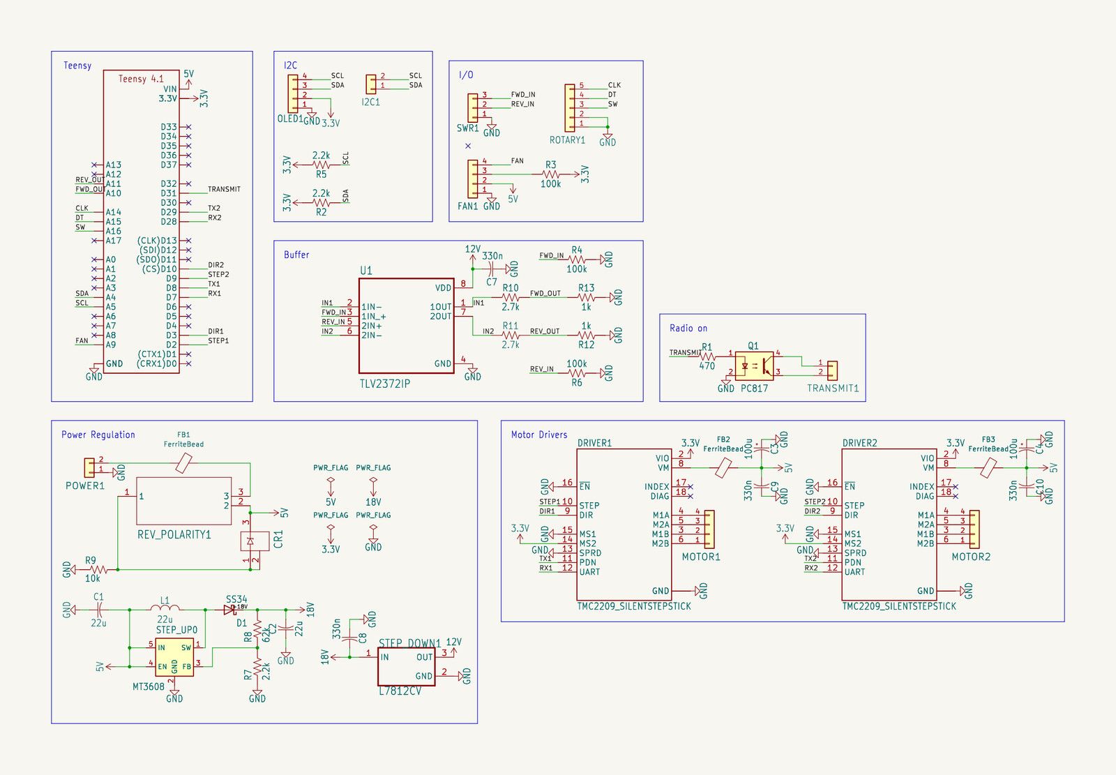
The control board connects the Teensy 4.1, stepper drivers, and VSWR sensing.
Sensor Integration
To measure VSWR, I reverse-engineered a COTS Surecom SW-112 VSWR meter and tapped into its internal toroidal sensing lines, then built an analog sensing path into the Teensy’s ADCs around it.
Source
Reverse-engineered Surecom SW-112 toroidal sense lines
Buffering
TLV2372IP op-amps isolate the Teensy ADC inputs
Line impedance
~1 MΩ high-impedance path, preserved to avoid loading the sense lines
Why it matters
Prevents voltage sag that would otherwise alter RF behavior mid-measurement
Firmware
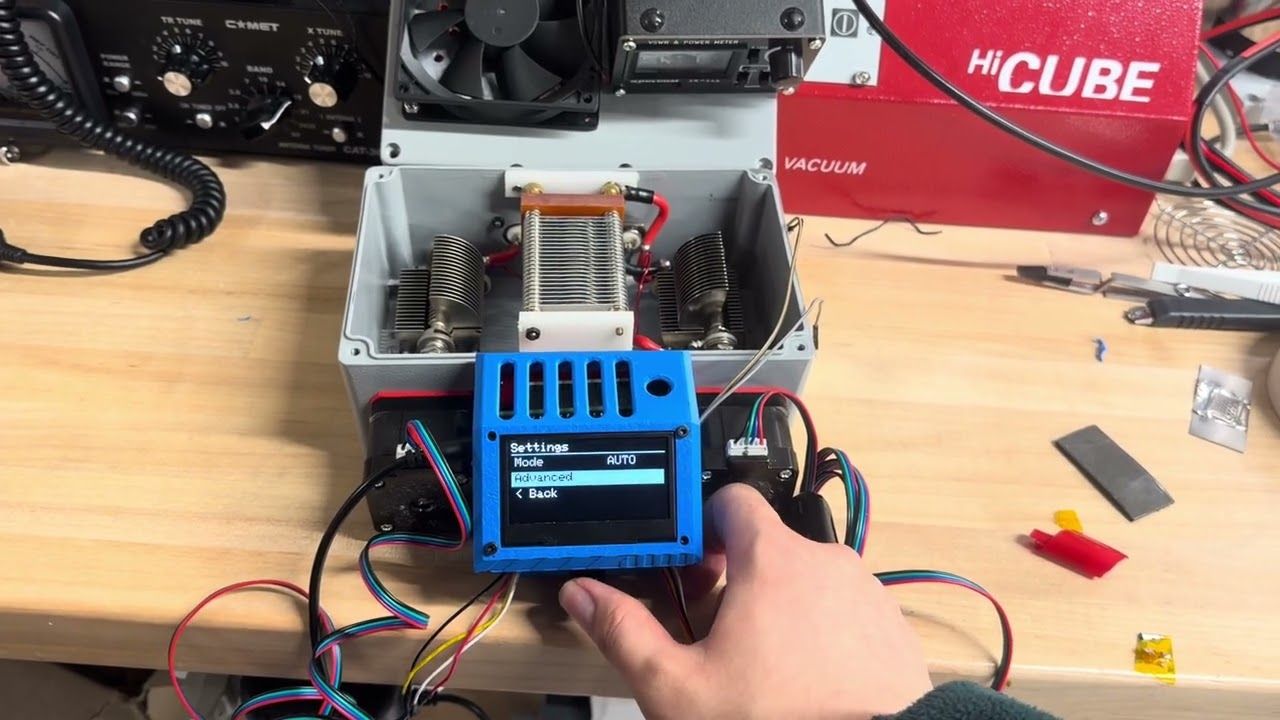
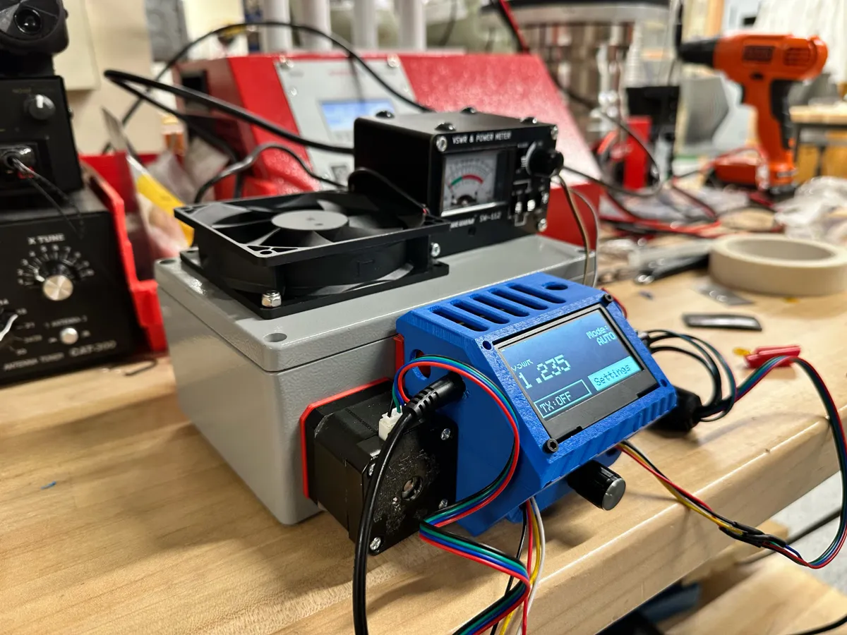
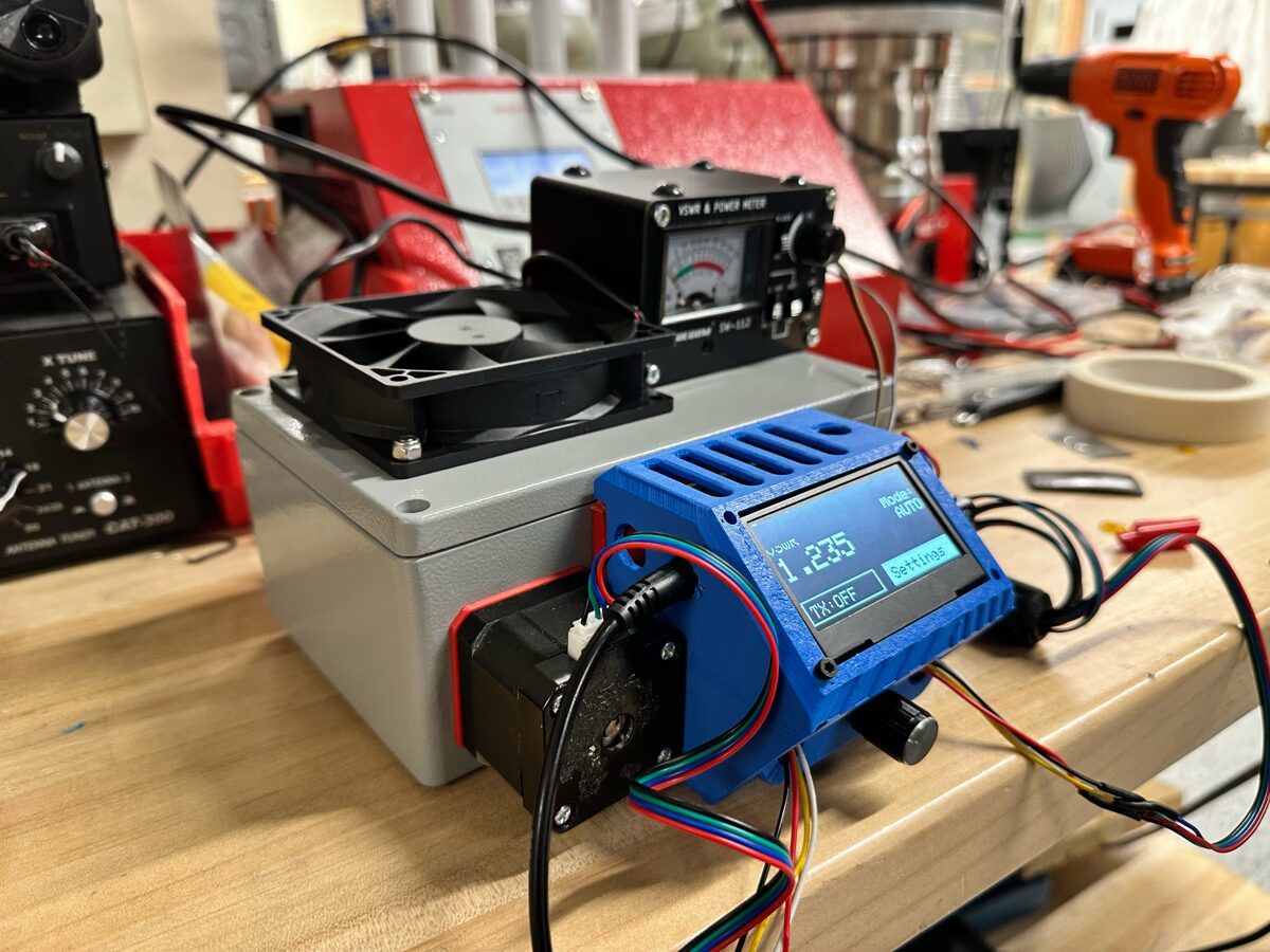
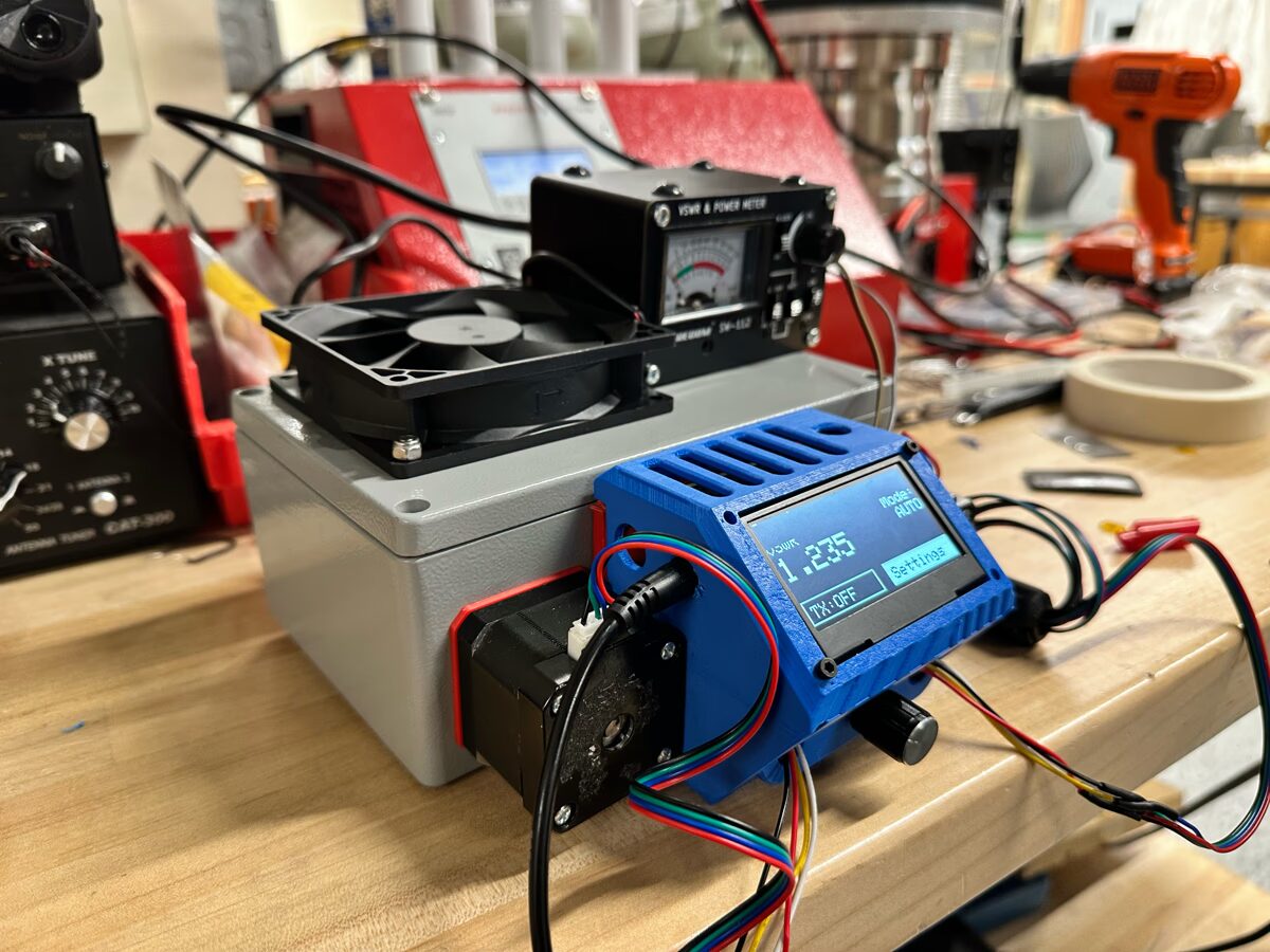
The firmware processes digitized forward and reverse power, runs the coordinate descent matcher, and drives the actuators in real time. I also built a local interface with an I2C OLED and rotary encoder so operators can switch between automated and manual tuning while monitoring VSWR and power telemetry.
Deployed impedance matcher showing VSWR on the OLEDExplore the hardware interfacePointerClick OLED buttons. Wheel or trackpad through Settings.TouchTap buttons. Swipe vertically through Settings and horizontally to adjust values.KeyboardUse arrows to navigate and Enter to select.
Control Algorithm
Each iteration, the firmware probes one motor axis at a time: it takes a small step, measures the change in cost, and uses the ratio as an approximate gradient to scale the next step.
Measurement / cost
VSWR=Vfwd + VrevVfwd − Vrev
J=(VSWR − 1)2
V is the mean of N = 300 ADC samples, supersampled to suppress 13.56 MHz switching noise.
Finite-difference step
g=ΔJΔθ≈−∇J
Δθcmd=α · g(α = 0.025)
Step clamp
Δθ∈[π700,π36]
Lower bound escapes the noise floor; upper bound keeps the small-step approximation valid.
Automated impedance matcher hardwareFollow coordinate descentModeled demonstration of the tuning path.PointerHover the plot to inspect the tuning path.TouchView the plotted steps toward minimum VSWR.KeyboardThe plotted path and outcome remain visible without interaction.
Results
During a deployed argon sputtering-chamber test, the matcher held lock until the plasma extinguished from pump brownout or debris, not matcher drift. The design is open-source for other Hacker Fabs to replicate.
Stabilized VSWR
≈1.2 at ~95–100 W forward during the deployed chamber test